Saturday, 10 October 2015

Water Level Indicator Electronics Project

Water Level Alarm Using 555 Timer

The 555 timer IC is an integrated circuit (chip) used in a variety of timer, pulse generation, and oscillator applications. The 555 can be used to provide time delays, as an oscillator, and as a flip-flop element. Derivatives provide up to four timing circuits in one package.

Introduced in 1971 by American company Signetics, the 555 is still in widespread use due to its low price, ease of use, and stability. It is now made by many companies in the original bipolar and also in low-power CMOS types


Specifications for 555

These specifications apply to the NE555. 
specifications depending on the grade (military, medical, etc.).
Supply voltage (VCC)                  4.5 to 15 V
Supply current (VCC = +5 V)          3 to 6 mA
Supply current (VCC = +15 V)       10 to 15 mA
Output current (maximum)             200 mA
Maximum Power dissipation           600 mW
Power consumption (minimum operating)     30 mW@5V, 225 mW@15V
Operating temperature                 0 to 70 °C


Here we are using a simple and low cost hardware using 555 Timer Circuit.
Our aim is to make a water level detecting alarm with simple and low cost hardware without compromising on the performance of the device.


Circuit Diagram of Water Level Alarm using 555 Timer


Water Level Alarm Using 555 Timer Circuit Diagram:


Circuit Diagram of Water Level Alarm using 555 Timer


The circuit uses a 555 timer in astable mode with R1=220 ohms, R2= 150 ohms and C1=1 uF.

We know, the frequency of operation of the IC 555 in astable mode depends on the values of R1, R2 and C1. By calculating the frequency of the given astable circuit, we get the frequency to be around 1.18KHz. 

The frequency at which it operates is in the audio frequency.

The 1K Resistor R3 whose ends are connected to pin-4 and ground disables the circuit by default and it enables when the water reaches its full level when the probes get dipped in water.

The two probes which are shown in the circuit should be kept at the high level for the water. The astable multivibrator in the circuit is normally disabled and it gets enabled only when the probes touch the water. 

The distance between the probes should be less than a few centimetres to ensure that the conduction between the probes will take place when water is touched to these probes. 

When the water level rises to the height of the probes, then the 555 circuit will get enabled and the output of the 555 timer produces a square wave output with a frequency of about 1.18Khz. 

This output is given to the mini loudspeaker which then beeps at an audio frequency of 1.18KHz.


The dual version is called 556. It features two complete 555s in a 14 pin DIL package.

The quad version is called 558 and has 16 pins. To fit four 555s into a 16 pin package the power, control voltage, and reset lines are shared by all four modules. Each module's discharge and threshold circuits are wired together internally

 
The Logic behind the project is simple, now its up to you that what changes can you make in the given project. For e.g. You can develop an android app and use a GSM module to get instant alert on your smart phone.

Before going to your exams check out Viva and Exam Tips to go well prepared

Friday, 9 October 2015

10 Tips For Viva And Practicals

10 Tips For Viva And Practicals


10 Tips For Viva And Practicals


Vivas and practicals are the most threatening events in an engineer's life. These are the toughest things he ever faces in his four years. There are numerous questions running into the mind before appearing for the practicals, like

Which experiment will I get to Perform?
How will be the external who is taking the Viva?
What if I get the Experiment I didn't study for?
What if I did not get the output? can viva save me?

All these questions are genuine and everyone goes through this phase.Here are some Tips for Viva and Practicals, it can help you to get better results.


Things you should try to follow few hours before appearing for the exam,


1) Calm down and breathe: Working yourself up is only going to make things worse, by stopping you sleeping and making you ill. Find a way to relax, be it yoga, running, meditation or video games; but find something to help you stay calm.

2) Do something fun: Don’t spend all your time studying. You still need to have fun, You want to be fresh on the day, so go out and have some fun (maybe a hangout with those friends you've neglected over the last months/ years) or Have a round of video games with your friends. Listening to light music may also help you feel relaxed.

3) Look Good: You might have had a hectic semester and you were not able to concentrate on your wardrobe, your clothes might be dull and not ironed since ages but take out some time and get your clothes through the laundry once. you should make proper efforts to dress smart on your viva day.Firstly, looking good will help your self-esteem, making you feel more confident. In some case there might be a dress code so don't mess yourself up.

4) Believe in yourself: You have spent the last few months reading about, writing about and doing your practicals. You are the expert; you know your stuff, remember that.

5) Sleep Well: You might not be prepared or you have lot of stuff to be completed or may be any other issue, don't let this affect your sleep, have a proper sleep before the examination day. A good night’s sleep is essential to stay fresh in body and mind.

10 Tips For Viva And Practicals


Something you should remember when you are in the examination hall. 


1) Take deep breaths: If you've been made to wait, have a glass of water and take some deep breaths so that your voice is regulated and you don’t seem shaky.Also, prepare a small talk you would be having at the beginning with the examiner. This is essentially to break the ice and you’re at ease instead of sounding like a diffident person.

2) Go in with a good attitude. Don’t see the examiners as evil torturers who get kicks out of making you suffer. They want you to pass. However, if you go in thinking that they want you to fail you’ll not only be more scared, you’ll also be more defensive, which isn't always a good thing. Instead try to think of your examiners as people who are really interested in what you have done and who understand all the problems and pitfalls associated with the experiment.

3) Give Your Best: Whatever you know about the presented question give your best, If you don't know the answer of the asked question just say "I don't know", do not try to fool the examiner (Remember that he knows more than you) answering wrong will have a bad impact rather than saying you don't know it.

4) If you feel you've failed: You really had a bad try at the experiment and you could not perform the given experiment. Do not panic, it will not take you anywhere, rather think what next you can do to get yourself out of the situation. A good viva after a really bad practical can increase the chances of your success.


Case Study on Barrel Shifter (Digital Signal Processing)

Case Study On Barrel Shifter


A barrel shifter is a block of combinational logic that takes an N-bit input value and provides as output the N-bit value shifted left or right by P bits. The great advantage of a barrel shifter is of course speed. It does in a single cycle what it would take P cycles to achieve in GPPs without a barrel shifter.
Right shifting in binary by P bits is really the same as division by 2P, and left shifting is the same as multiplication by 2P.

Figure illustrates the generic architecture of a barrel shifter. The main functions of a shifter in a DSP are summarized as follows:

1. Pre and/or Post scaling:
  • To maintain accuracy without the benefit of a floating-point data path, fixed-point DSP processors have a good support for shifting operations. Many DSPs provide barrel shifters at both the input (pre-scaling) and output (post-scaling) of their MAC logic. 
  • The pre-scaler is generally activated by a pseudo instruction used in the code, for example, MACD, X, Y, 4, which divides the input data by 4 BEFORE the multiply occurs. The coefficient remains unaltered. 
  • An output post-scalar is generally set up prior to execution of a block of code (i.e., digital filtering, convolution, or an FFT) in order to scale the output data from the MAC operation by a specific factor. 
  • This is intended to reduce the probability of overflows, which can occur during long sequences of MAC operations. 
  • Use of this automatic scaling technique partially eliminates the overheads otherwise incurred when having to check your results for overflow and underflow (the DSP generally provides one or two flags, which need to be checked manually for overflow and underflow by your program after each MACD execution). 
  • If an overflow is indicated, you can either abort the program or recalculate the results.
2. Normalization & De normalization:

  • It is indicated, you can either abort the program or recalculate the results.
  • Normalization involves conversion from fixed point to floating point systems by generation of mantissa and exponent.
  • This is a two process. 
  • The first one involves exponent detection which calculated the number of shifts needed. 
  • The next step provides this value to the shifter for actually shifting the number. De normalization involves conversion of floating point into fixed point systems i.e. inverse of normalization. 
  • The exponent provides number of shifts required in the mantissa.
3. Block floating point:

  • A block floating-point format enables a fixed-point processor to gain some of the increased dynamic range of a floating-point format without the overhead needed to do floating-point arithmetic. However, some additional programming is required to maintain a block floating-point format. 
  • It can also be used in floating point processors.
Barrel Shifter

DATA ADDRESS GENERATORS


  • Super Harvard Architecture with modifications is the most suited architectures for DSPs. 
  • Such an architecture has multiple busses to access the memory viz. Data memory bus & program memory bus.
  • This is obviously an advantage with respect to increase in speed but this would demand additional hardware that would keep track of address on each of these busses. 
  • The Data Address Generator (DAGs) keeps a track of the addresses of the input data and the coefficients that are stored in the data and program memories respectively. 
  • Now the CPU no longer has to bother about the addresses of the data, the DAG will do that task. 
  • This is most useful when a set of addresses are used repeatedly, for example, scanning a data array or in FFT computations. 
  • The address generation unit would require its own arithmetic unit to increment or decrement the addresses, and/or to add/subtract offsets from the base address in case of nonsequential addresses. 
  • The increment/decrement step size for address in each case can be predefined as 1,2,4 or 8 and so on depending upon the size of each data item. Any DAG would require at least the following types of registers. The types of registers are:
•Index registers: An index register holds an address and acts as a pointer to memory.

•Modify registers: A modify register provides the increment or step size by which an index register is pre- or post-modified during a register move.

•Length and Base registers: Length and base registers setup the range of addresses and the starting address for a circular buffer. These registers hold the values that the DAG uses for generating addresses.

How to configure DSP processor

Case study of Interpolation and Decimation (Digital Signal Processing)

Case study of Interpolation and Decimation


THEORY

Sampling:


Sampling is the process of representing a continuous signal with a sequence of discrete data values. In practice, sampling is performed by applying a continuous signal to an analog-to-digital (A/D) converter whose output is a series of digital values

A variety of techniques have been developed to efficiently represent speech

signals in digital form for either transmission or storage. Since most of the speech

energy is contained in the lower frequencies, we would like to encode the lower frequency
band in more bits than the high-frequency band. Sub-band coding is a
method where the speech signal is subdivided into several frequency bands and
each band is digitally encoded separately.

 Downsampling (Decimation):


Decimation is a technique for reducing the number of samples in a discrete-time signal.

The operation of downsampling by factor M describes the process of keeping every Mth sample and discarding the rest. This is denoted by ” ↓M ↓ M ”


Upsampling (Interpolation):


Interpolation is a technique for increasing the number of samples in a discrete-time signal. The operation of upsampling by factor L describes the insertion of L-1 L 1 zeros between every sample of the input signal. This is denoted by “↑L ↑ L “in block diagrams, as in figure.


Basics
 
An example of a frequency subdivision is shown in the Figure 1. Let us
assume that the speech signal is sampled at a rate Fs samples per second. The first
frequency subdivision splits the signal spectrum into two equal width segments, a
low pass signal (0 < F < Fs/4) and a high pass signal (Fs/4 < F < Fs/2).

The second frequency subdivision splits the lowpass signal from the first
stage into two equal bands, a low pass signal (0 < F < Fs/8) and a high pass signal
(Fs/8 < F < Fs/4). Finally, the third frequency subdivision splits the low pass signal
from the second stage into two equal bandwidth signals. Thus, the signal is
subdivided into 4 frequency bands, covering 3 octaves, as shown in the figure.

Decimation by a factor of 2 is performed after frequency subdivision. By
allocating a different number bits per samples to the signals in the 4 sub-band, we
can achieve a reduction in the bitrate of the digitalized speech signal.

Check out Viva and Practical tips which will boost your confidence


Frequency Subdivision
Block Diagram: Sub band Speech Coder
Synthesis of Sub band Encoded Signal

Sub band coding of speech signal or application of Multirate processing in
DSP: simply we are decimating the signal i.e. decreasing the sampling rate at the
Transmitter, As all of us know Bandwidth Constraint is the main concern in Digital
Signal Processing. By decimating the signal at the Transmitter; it can be transmitted
with less number of Bits: ultimately results in saving the Bandwidth. 

While at the time of Reconstruction the signal is interpolated by the same factor, to achieve the original one.
The system at Transmitter and Receiver (Encoder and Decoder can be implemented using DSP Processor TMS 320 C 6713)


If you have any kind of doubts or queries please commment below and we well reply to your comment withing 24 hours thats entcengg promise.

Tuesday, 29 September 2015

File System Interface In Operating System Ppt/Pdf/Ebook Download

File System Interface

  • File Concept
  • Access Methods
  • Directory Structure
  • File System Mounting
  • File Sharing
  • Protection

File Concept


  • Contiguous logical address space

Types:

  • Data
  1. numeric
  2. character
  3. binary
  • Program

File Structure


  • None - sequence of words, bytes
  • Simple record structure
  1. Lines 
  2. Fixed length
  3. Variable length
  • Complex Structures
  1. Formatted document
  2. Relocatable load file 
  • Can simulate last two with first method by inserting appropriate control characters
  • Who decides:
  1. Operating system
  2. Program

File Attributes

Name: only information kept in human-readable form.

Type: needed for systems that support different types.

Location: pointer to file location on device

Size: current file size

Protection: controls who can do reading, writing, execution.

Time, date, and user identification:data for protection, security, and usage monitoring

Information about files are kept in the directory structure, which is maintained on the disk

File Operations

Create
Write
Read
File seek – reposition within file
Delete
Truncate
Open(Fi) – search the directory structure on disk for entry Fi, and move the content of entry to memory
Close (Fi) – move the content of entry Fi in memory to directory structure on disk

Open Files:

Several pieces of data are needed to manage open files:
  1. File pointer:  pointer to last read/write location, per process that has the file open
  2. File-open count: counter of number of times a file is open – to allow removal of data from open-file table when last processes closes it
  3. Disk location of the file: cache of data access information
  4. Access rights: per-process access mode information

Open File Locking:

  • Provided by some operating systems and file systems
  • Mediates access to a file
  • Mandatory or advisory
  1. Mandatory – access is denied depending on locks held and requested
  2. Advisory – processes can find status of locks and decide what to do

File Locking Example – Java API


import java.io.*;
import java.nio.channels.*;
public class LockingExample { 
public static final boolean EXCLUSIVE = false;
public static final boolean SHARED = true;
public static void main(String arsg[]) throws IOException { 
FileLock sharedLock = null;
FileLock exclusiveLock = null;
try { 
RandomAccessFile raf = new RandomAccessFile("file.txt", "rw");
// get the channel for the file
FileChannel ch = raf.getChannel();
// this locks the first half of the file - exclusive
exclusiveLock = ch.lock(0, raf.length()/2, EXCLUSIVE);
/** Now modify the data . . . */
// release the lock
exclusiveLock.release(); // this locks the second half of the file - shared

sharedLock = ch.lock(raf.length()/2+1, raf.length(), SHARED);

/** Now read the data . . . */
// release the lock
exclusiveLock.release();
} catch (java.io.IOException ioe) { 
System.err.println(ioe);
}finally { 
if (exclusiveLock != null)
exclusiveLock.release();
if (sharedLock != null)
sharedLock.release();
}
}
}


Copy the above code


File Types – Name, Extension

file type name extension

Access Methods:

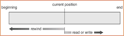
Sequential Access:
                read next
write next 
reset
no read after last write
        (rewrite)

Direct Access:
read n
write n
position to n
read next
write next 
rewrite n
n = relative block number


Sequential-access File:

Sequential access File

Simulation of Sequential Access on a Direct-access File


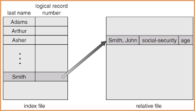
Example of Index and Relative Files

Example of Index and Relative Files

Directory Structure

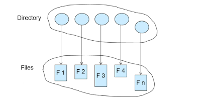
A collection of nodes containing information about all files

Directory Structure

Both the directory structure and the files reside on disk
Backups of these two structures are kept on tapes


A Typical File-system Organization

A Typical File system Organization

Information in a Device Directory

  • Name 
  • Type
  • Address 
  • Current length
  • Maximum length
  • Date last accessed (for archival)
  • Date last updated (for dump)
  • Owner ID
  • Protection information (discuss later)

Operations Performed on Directory

  • Search for a file
  • Create a file
  • Delete a file
  • List a directory
  • Rename a file
  • Traverse the file system

Organize the Directory (Logically) to Obtain:

  • Efficiency – locating a file quickly
  • Naming – convenient to users
  1. Two users can have same name for different files
  2. The same file can have several different names
  • Grouping – logical grouping of files by properties, (e.g., all Java programs, all games, …)

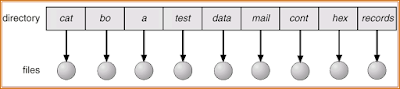
Single-Level Directory

A single directory for all users

A single directory

Naming problem
Grouping problem

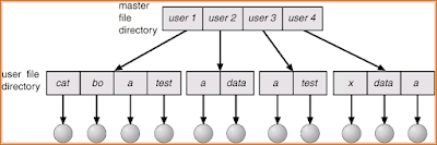
Two-Level Directory


Separate directory for each user


Two Level Directory

  • Path name
  • Can have the same file name for different user
  • Efficient searching
  • No grouping capability

Tree-Structured Directories

Tree Structured Directories

Efficient searching
Grouping Capability
Current directory (working directory)
  • cd /spell/mail/prog
  • type list
Absolute or relative path name
Creating a new file is done in current directory
Delete a file
rm <file-name>
Creating a new subdirectory is done in current directory
mkdir <dir-name>
Example:  if in current directory   /mail
mkdir count
Tree Structured Directories

Deleting “mail” deleting the entire subtree rooted by “mail”


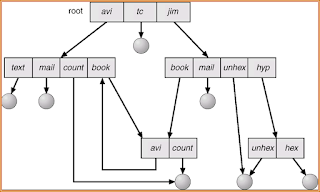
Acyclic-Graph Directories:

Have shared subdirectories and files
Acyclic Graph Directories

Solutions:
  • Backpointers, so we can delete all pointers Variable size records a problem
  • Backpointers using a daisy chain organization
  • Entry-hold-count solution

General Graph Directory

General Graph Directory

  • How do we guarantee no cycles?
  1. Allow only links to file not subdirectories
  2. Garbage collection
  3. Every time a new link is added use a cycle detection algorithm to determine whether it is OK

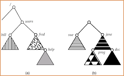
File System Mounting

  • A file system must be mounted before it can be accessed
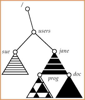
  • A unmounted file system is mounted at a mount point
(a) Existing.  (b) Unmounted Partition

file system mounting

Mount Point

Mount Point

File Sharing

  1. Sharing of files on multi-user systems is desirable
  2. Sharing may be done through a protection scheme
  3. On distributed systems, files may be shared across a network
  4. Network File System (NFS) is a common distributed file-sharing method
File Sharing – Multiple Users

User IDs identify users, allowing permissions and protections to be per-user
Group IDs allow users to be in groups, permitting group access rights

File Sharing – Remote File Systems

  • Uses networking to allow file system access between systems
  1. Manually via programs like FTP
  2. Automatically, seamlessly using distributed file systems
  3. Semi automatically via the world wide web
Client-server model allows clients to mount remote file systems from servers

  • Server can serve multiple clients
  • Client and user-on-client identification is insecure or complicated
  • NFS is standard UNIX client-server file sharing protocol
  • CIFS is standard Windows protocol
  • Standard operating system file calls are translated into remote calls

Distributed Information Systems (distributed naming services) such as LDAP, DNS, NIS implement unified access to information needed for remote computing

File Sharing – Failure Modes

  • Remote file systems add new failure modes, due to network failure, server failure
  • Recovery from failure can involve state information about status of each remote request
  • Stateless protocols such as NFS include all information in each request, allowing easy recovery but less security

File Sharing – Consistency Semantics

Consistency semantics specify how multiple users are to access a shared file simultaneously
  • Similar to Ch 7 process synchronization algorithms
  • Tend to be less complex due to disk I/O and network latency (for remote file systems
  • Andrew File System (AFS) implemented complex remote file sharing semantics
  • Unix file system (UFS) implements:
  • Writes to an open file visible immediately to other users of the same open file
  • Sharing file pointer to allow multiple users to read and write concurrently
  • AFS has session semantics
  • Writes only visible to sessions starting after the file is closed

Protection

File owner/creator should be able to control:
  • what can be done
  • by whom
Types of access Read
  1. Write
  2. Execute
  3. Append
  4. Delete
  5. List

Access Lists and Groups

Mode of access:  read, write, execute
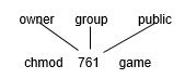
Three classes of users

Ask manager to create a group (unique name), say G, and add some users to the group.
For a particular file (say game) or subdirectory, define an appropriate access.

access list and groups


Your questions and feedback is valuable to us and we will be more than happy to answer your queries. Like our Facebook Page.

More related posts:
1) Linkers and loaders 
2)Two pass assemblers 

Linkers, Loaders and Software

Linkers  Loaders  Software


Linkers and Loaders:

Basic loaders functions, central loaders scheme, absolute loaders, Subroutine linkers, relocation loader, Direct linking loader, Dynamic linking loader,

Design of absolute loaders and direct linking loader

Software tools: Software tools for program development, editors, debug monitor, programming environment, user interfaces.


Software Tools for program Development

Software tools are used extensively for program development and user interfaces
  • Editor
  • Debug monitor
  • Programming Environment
  • User Interfaces
Editor
Editor is computer program that allows a user to create and revise target document

Document includes object as computer programs, text, equations, tables, diagrams, lines and photographs.

The document editing process is an interactive user-computer dialogue

1.Select the part  to view and manipulate
2.To determine the format of and display
3.Specify and execute operation

4.Update the view appropriately

Text editor are of following types
  1. Line Editors
  2. Sreen Editors
  3. Word processors
  4. Structure Editiors

Line Editors

  • Text editor are of following types
  • It is primitive form of editor
  • User has to specify line to change text
  • Interaction with the editors is through a set of commands , this makes a editor less user friendly
  • E.g. VI editor, VIM editor

Screen Editors


  • Screen editors enables to modify any text by moving cursor to desired location.
  • This is very useful while formatting the text to produce printed document
  • E.g. office document.

Word processor

  • A word processor recognize word a basic entity
  • It support spell check option
  • It has following options
1.Moving a section of text from one place to another
2.Delecting a section of text
3.Searching a word
4.Merging of text
5.Replacement of word
6.Spell-Check

Structure Editors

  • A structure editor has awareness of structure of document.
  • A structure is specified by user while creating and modifying the document.
  • E.g.   LatTex

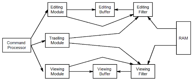
Editor Structure

structure of an editor

  • Editing module is collection of module deling with editing tasks.
  • Travelling module of editor performs the setting of the current editing and viewing pointers
  • In viewing module start of the area to be view is determine by current viewing pointer

Debug Monitor

  • Debug monitor provides following facilities
  1. Setting breakpoints in the program
  2. Initiating a debug conversation
  3. Displaying values of variables
  4. Assigning new values to variable
  • Debugging system provides functions such as tracing and trackback.
  • Tracking used to track the flow of execution logic and data modification
  • Trackback can show path by which the current statement reached
  • In debugging user specifies breakpoints and action to be performed

Programming Environment

  • Programming environment is an integrated program development environment
  • It has following facilities
  1. Program creation
  2. Editing
  3. Execution
  4. Testing and debugging
Programming Environment has following components 
     1. A syntax directed editor
     2.Compiler ,Interpreter
     3.Debug monitor
     4.Dialog monitor

User Interfaces

  • A user interface plays an important role in simplifying the interaction of user with application
  • UI functioning has two important aspects
  1.  Issuing Commands
  2.  Excange of data 
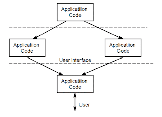
working of user interface

  • The presentation manger is responsible for managing user’s screen and for accepting data
  • The dialog manager is responsible for interpreting user command and implement them
  • Dialog manger is also responsible for  error message

More related posts:
1) Deadlock

 2)Two pass assemblers 

Saturday, 26 September 2015

10 Unexpected Interview Questions and Answers

10 Amazing Interview Questions and Answers


Here are some really weird interview questions which will catch you off guard. The main aim of the interview is not to test your skills and technical knowledge but to test how you react to a panic situation.

They try throw random questions at you and you just need to listen the question properly and think over it twice before answering, If you panic and answer randomly without thinking over it much Bang…! You are out.


Here are some questions asked in job interviews which were really tricky and lets learn how to answer interview questions


Interview Questions and Answers

When patriotism hit high


Panelist 1: Do you know who wrote the Indian National Anthem?

Student's reply: Yes Sir, Rabindranath Tagore

Panelist 1: Ok, sing it now.

Student: [Stood up] Jana Gana Mana…

Panelist 2: Stop, otherwise we have to stand up too.

Result: Failed


Here is another incident which really shows how you could be targeted


When Delhi elections took a toll.


(Background:A guy was screaming a lot in the Group Discussion as well as the interview. Around the time of my interviews, During the New Delhi elections were going on where Kiran Bedi had referred to Arvind Kejriwal as 'Upadravi' for being an anarchist)


Somewhere during the interview,

Panelist 1 (in Hindi): Upadravi gotr ke ho kya?


Student: Sorry sir, I didn’t get that.

Panelist 2 (while going through my marksheets): Rehne do, isko samajh nahi aayega, 10th mein Hindi mein kam marks hain.

Student: Banged his head.

Result: Rejected.


When the question of dowry was brought to the table


Interviewer 1: Why are people poor?

Student: Not very sure, sir. Any options?

Interviewer 2: Oh! But you should know. It’s because they don’t have money. It’s simple.

Student:… Apologies Sirs, but isn’t this the ‘meaning’ of being ‘poor’, and not the reason?

Interviewer 2: (Silent)

Interviewer 1 (in his excitement to go one-up): “… He’s poor because he’s not earning. Hence, no money.”

Student: "apologies Sirs again. But is he poor because he is not earning out of laziness, or he is working and not being paid, or, is he ready to work and earn, but is not getting a job.”

Interviewer 1: Have you studied Economics in your B.Tech?

Student: “No, sir our canteen supervisor in the hostel is really poor, and he has a Master’s in English”

Result: Approved.


When the love of Math took over


Panelist: You seem to know a lot of math. What do you like in it?

Student: I like numbers, Sir.

Panelist: Ok. So tell us, what is the absolute truth?

Student: (Wow, what? Where did that come from and how is that related to numbers.) How would I know, Sir? I’m just a human being. They say God knows the absolute truth.

Panelist: Ok then, define God mathematically.

Student: Sir, God is the One. (They smile).

Result: Selected.


Too much randomness


Panelist: Spell the word COW in thirteen letters?

Candidate: Well! Caaaouuuuu.

Panelist: It’s “SEE O DOUBLE YOU”


When Comparison between 2 B-schools took over


Panelist 1 (male): What do you know about IIM Calcutta?

Student: *Gave a standard well-versed answer mostly from the content on their website*

Panelist 2 (female): Okay, tell me what do you know about IIM Bangalore?

Student (taken by surprise): Annn.. Ma’am, it is one of the best B-schools in the country. (Clueless about what more should I add)

Panelist 2: So you know more about Calcutta than Bangalore? Didn’t you get a call from IIM Bangalore?

Student: Ma’am, I do have the call from IIM Bangalore, but its interview is two weeks later. (With a poker face)

Result: Selected.


When Everything was kept aside and the question that lingered on was about email ids.

 Panelist 1: So tell me Abhishek why do you have ‘1993’ in your email-id?

Student: Sir, I needed a bit more professional id as compared to my previous one.

Panelist2: So what was your previous id?

Student: Sir, it was abhishek.perfect@yahoo.com <smiling like an idiot>

<Both laughing at me>
Panelist 2: So you think you are not perfect anymore?

*Suddenly the pseudo-intellectual philosopher in me wakes up*

Student: Sir, even the air around me is not ideal, how can I be perfect.

Result: Selected.


When things got way too philosophical


Interviewer: Tell me anything you know whose heading will surprise me and the explanation will shock me. More the impact, more will be your chances of success. Heading and Explanation both can be independent.

Student: Let me try. First of all, tell me what are you fascinated about?

Interviewer: Ok! From my childhood, I was really fascinated about my existence. What am I made of? Why am I here? These types of stuff.

Student: Why you did not choose a career in research?

Interviewer: There are things that are beyond our explanation. Well, answer my question.

Student: Do you know that the life we live is 50% dream and 50% reality?

Interviewer: You are successful. Explain?

Student: Something else. An electron is neither revolving around the nucleus in circular path nor in elliptical paths. It is something like a bee hovering around her honey.

Result: Selected

When someone asks you to draw intersecting parallel lines


 Interviewer: What is the sum of angles of a triangle?

Student: Sir, um, interior angles or exterior angles?

Interviewer: Interior.

Student: 180

Interviewer: Can there be two lines which are parallel and not intersecting?

Student: Sir, can you please repeat the question?

Interviewer: Draw and show it to me.” (Passed a paper and a pen)

Student: Again, after thinking for some time: I can’t, I need a ruler.

Result: Selected


When the question of dowry was brought to the table


Panelist 1: Why exactly do you want to come to this campus, because I feel that it has nothing to do with what we offer but just that you want to go home and brag about getting the admission here to your friends and parents and get a large dowry later on. Why do you want to get here?

Student: I am not aware of the dowry part. But if what you say is correct, I shall surely go back home and renegotiate.

(The interviewer bursts out laughing)

Student:  I really want to be here. Period. 

Friday, 25 September 2015

What Is A Loader?

LOADER


Definition of Loader:

  1. Loader is a system program which is responsible for preparing the object file to start the execution.
  2. Once the assembler produces an object program,that program must be placed into memory and executed. It is the purpose of the loaders is to assure that object programs are placed into an executable form.
Functions of Loader:
1.  Allocation 
  • Allocates space in memory for the program.
  • In case of Absolute ALP allocation is done by programmer.
  • In case of  Relocatable ALP allocation is done by loader.
2. Linking
  • Resolve symbolic references between objects.
  • In case of Absolute ALP linking is done by programmer since,
  • programmer is aware of runtime address of all symbols.
  • In case of  Re locatable  ALP allocation is done by loader and hence assembler must provide the location at which linking is to be done.
3. Relocation
  • Adjust all address dependant locations,such as address constant to correspond to the allocated space.
  • In case of Absolute ALP this is done by assembler. In case of Relocatable ALP this is done by loader.
4. Loading
  • Placing the object program into its assign memory location.
  • In both the cases this is done by the Loader.
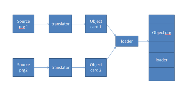
General Loading Scheme:
general loading scheme

  1. In this, source program is translated into object program using assembler.
  2. Then it is loaded into main memory along with source code of loader.
  3. Size of loader is smaller than assembler code  therefore , more  space is available for the object program.
Disadvantage
We have to store source code of loader.


Absolute Loader:
  • The absolute loader reads the object program line by line and moves the text of the program into memory.
  • Object program has
  1. Machine instruction with memory address
  2. Starting of execution point
 It requires 2 types of  records
i ) Text Card
It contains binary image of assembly program
ii) Transfer Card
It contains starting point execution.
 
1)TXT Card:
TXT card
 
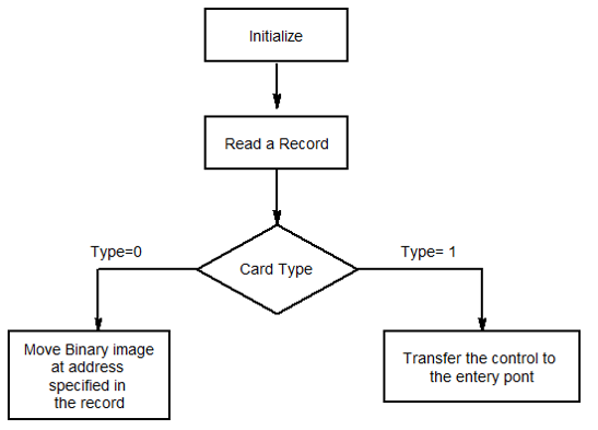
Card Type: It indicate which type of card
0 for Text card.
1 for Transfer card.
2.Count: It indicates amount of information which is to be loaded.
3.Address: It indicates location at which information is to be loaded.
4 Content: It indicates binary information which is to be loaded.

Transfer Card:
Transfer Card: It is used to indicate where to be load the program
Card type is 1.
Count is always 0.
Address: It indicate location from where execution of object program should begin.
Content: It always kept blank.

 
Algorithm

algorithm transefer card  
 
Bootstrap Loader
  1. Program residing in EPROM,ROM or other non-volatile memory
  2. Automatically executed by the processor
  3. Reads the hard disk drives boot sector to continue the process of loading the computer OS
Function of Bootstrap Loader: 
  1. Enable the user to select the OS to start
  2. Loading the OS file from the boot partition
  3. Controlling the OS selection process and hardware detection prior to kernel initialization.
 DLL : Direct Linking Loader
  1.  It is Relocatable type of loader.
  2. It has advantage of allowing programmer with multiple procedure segments and giving them complete freedom of referring data contained in some other segment.
  3. Input to the loader is set of object programs to be linked together
  4. This provides flexible Intersegment Referencing, for doing all this, DLL required following modules.
    1.  ESD-External Symbol Directory
    2. TXT-Actual assembled program
    3. RLD-Relocation and Linkage directory module
    4. END-End module


1:ESD-External Symbol Directory

ESD card contains information about all symbols that are define in a program that may be referred somewhere else and vice versa.
There are  3 types of symbols
  1. Segment Definition (SD):-It is name of the program which return prior to start keyword.
  2. Local Definition (LD):-This are the symbols which are define in the program.External
  3. Reference(ER):- This are symbols which are referred in the program but are defining somewhere else.
ID: - Giving unique no. to all segment definition and external reference.
Relative Address:- It is address at which those symbols are define.
Length: - Size of the symbol.

2. TXT Card
TXT card
Text portion of object module contains the relocatable machine language instruction and data that were produced during translation.

RLD (Relocation and Linkage Directory card)

It contains information about those location of the program whose contains depend on address at which the program is placed.
It contains following information:
  1. The address of each operand that needs to be changed due to relocation
  2. By what it has to changed
  3. The operation to be performed
End Card


It specifies that start of execute of the of the object program and end of object module.


Design of DLL (Direct Linking Loader) :
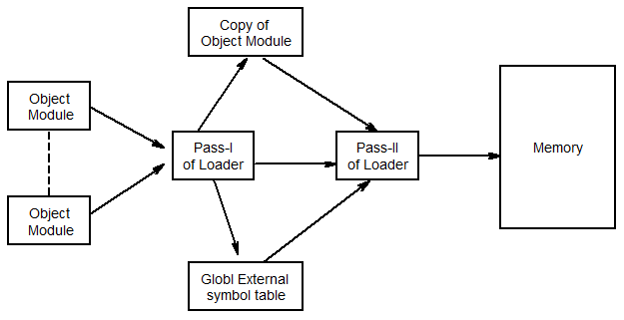
  • Direct linking loader requires two passes to complete the linking process
  • Pass-I assigns address to all external symbol
  • Pass-II performs actual loading ,relocation and linking
In pass-I global external symbol table is prepared which has external symbol and corresponding absolute address value.

Two Pass Loader scheme 

Two Pass Loader scheme


Pass1 Database
1. Object card: - This card contain object program in four cards.
i. ESD
ii. TXT
iii. RLD
iv. END

IPLA (Initial program Local Address):-It is the address obtained by loader from operating system.
 

GEST (Global External Symbol Table):- It is used to keep track of addresses that are assign to the symbol.
Copy file:- it is preferred by pass1 to be used by pass2.
Load Map:- It is printed listing of GEST table.

 Pass2 Database
Copy file:- it is preferred by pass1 to be used by pass2
 

IPLA (Initial program Local Address):-It is the address obtained by loader from operating system.
 

Execution Address (EXADDR):- It indicates the location from where the execution of object program should begin.
 

GEST (Global External Symbol Table):- It is used to keep track of addresses that are assigning to the symbol.
 

Local External Symbol Array(LESA):- It is prepared with the help of  ESD And GEST.

Entc Engg. Powered by Blogger.